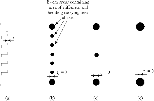
STRUCTURAL IDEALISATION
In the work done so far, the aircraft structural components analysed have been relatively simple.However an aircraft wing (for example) can be made up of many cell compartments. Each
section of the wing would be covered by a thin skin, and the skins would be reinforced by many
stringers of Z, C or T section. The analysis of such a structure would be extremely complex and
time consuming. In order to simplify this, structural idealisation should be carried out.
STRUCTURAL IDEALISATION
1) The longitudinal stiffeners and spar flanges carry only axial stresses
2) The web, skin and spars webs carry only shear stresses
3) The axial stress is constant over the cross section of each longitudinal stiffener
4) The shearing stress is uniform through the thickness of the webs
5) Transverse frames and ribs are rigid within their own planes and have no rigidity
normal to their plane.
looks something like this:
|
Figure 54: Original and Idealised wing sections |
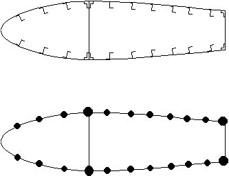
- The stiffeners are represented by circles called booms, which have a concentrated mass
in the plane of the skin. - The direct stresses are calculated at the centroid of these booms and are assumed to have
constant stress through their cross-section.
- Shear stresses are assumed uniform through the thickness of the skins and webs.
- The direct stress carrying capability of skin is represented as an addition to existing
booms or as additional separate booms.
Because the skin can carry some direct load, usually tensile (although some can be carried in
compression but this is determined by the buckling load of the skin), the Direct Stress Carrying
Thickness of the skin is defined as:
tD = Actual skin thickness t, if skin resists totally direct load
tD = Percentage of t, if partially resists applied load
tD = 0 if skin only able to resist shear load
We now need to look at how these idealisation techniques can be applied:
Look at a typical stiffened panel:
|
Figure 55: a) Actual panel,b) Idealised panel with same number of |
To idealise a structure you can:
1) Replace the spar web by replacing its area to the major booms
2) Reduce the number of stiffeners or booms by combining the stiffener mass with that of
the skin into one boom
If you wish, this could be simplified even further by:
1) Increasing the cross-sectional area of just two of the booms with the direct carrying
capacity of the skin and stiffeners.
REMEMBER : When idealising a structure, the elastic characteristics of the idealised
structure must be the same as for the original structure.
IDEALISED SHEET TO SUPPORT TENSILE LOAD P
|
|
|
Figure 56: Actual sheet to be Idealised. |
Figure 57: Idealised structure. |
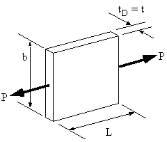
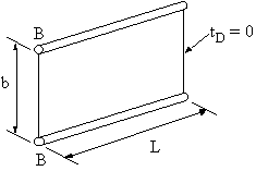
to do this two things must be considered, force (stress) equilibrium and compatibility
(displacement) In the real structure the direct stress is determined using:
![]()
![]()
![]() (in the Booms)
(in the Booms)![]()
![]()
relationship:

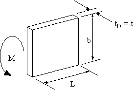
IDEALISED SHEET TO SUPPORT BENDING MOMENT M
The bending moment is applied at the end of the plate as follows:
|
Figure 58: Actual sheet to be idealised with applied bending moment M. |
![]()
![]()

different loading condition.
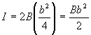
IDEALISED SHEET TO SUPPORT DIRECT LOAD AND BENDING MOMENT
The stress distribution for a combined loading case with a direct load and a bending momentlooks like Figure 59.
|
Figure 59: Actual sheet supporting direct load and bending moment. |
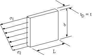
as actual direct stresses, Figure 60.
|
Figure 60: Idealised sheet supporting maximum stresses in booms. |
![]()
bending moment carried by the idealised structure must be the same as that carried by the real
structure. Equating moments about neutral plane gives the following:
![]()
![]()

WARNING : There is a problem with equations (6.3). It has to do with idealising sections of
skin very close to the neutral axis of the cross section, see Figure 61.
|
Figure 61: Skin segment very close to Neutral Axis to be idealised into booms i & j |
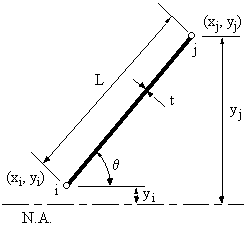

for the boom area.
To correct this problem, use the following correction. However be aware that this is just a
simplified correction method and that large errors can obtained if proper care is not taken to
observe how these corrections alter the solution.
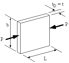
IDEALISED SHEET TO SUPPORT DIRECT COMPRESSIVE LOAD
When supporting a compressive load, the metal sheet is usually critical in buckling. Becauseof this, only a small fraction of its width 'b' is effective in compression. Experimental research
has led to the derivation of the following equations for the effective area of skin in compression.
|
|
|
Figure 62: Sheet to be idealised in compression. |
Figure 63: Idealised sheet. |


compression is valid, it is sometimes better to idealise the structure using the equations
derived for the other three load cases. When the stresses on the metal skin are known
we can then use critical buckling stresses for thin metal sheets to determine if they will
be effective in compression.
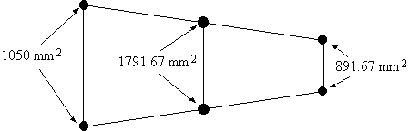
Example 7 : Part of a wing section is in the form of a two-cell box shown. All the vertical
spar webs are connected to the skins through spar caps, all with cross-sectional
areas of 300 mm2. Idealise the section into direct stress carrying booms and
shear stress only carrying skin when the wing is subjected to an applied bending
moment Mx = -150 kNm. Position the booms at the spar/skin junctions.
|
Figure 64: Wing section to be idealised,subject to a bending |
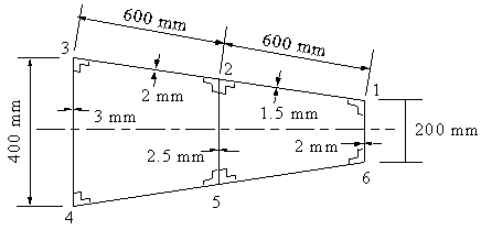
moment, equation (6.4) is the ones to use when idealising this section. Now, from symmetry : B1 = B6, B2 = B5 and B3 = B4, saving us some calculations. This would
not be the case if the wing wasn't symmetrical. Lets start with determining the area of boom 1. This boom must have first of all the area of spar cap 1, which is 300 mm2, together with the area
contributions of the two adjacent skins. Therefore:
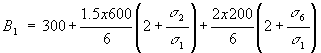
rations of their vertical distances. Which gives:
skins. Giving :
![]()
![]()
|
Figure 65: Final idealised wing with boom areas marked. |
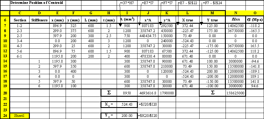
pages will carry out the same example but using table format, specifically using the program
Excel.
|
Figure 66: Excel sheet where the sectional properties and stresses of the real structure are calculated. |
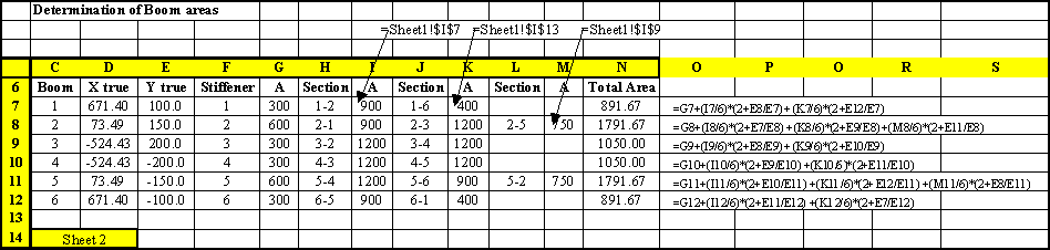
|
Figure 67: Excel sheet where the boom areas are calculated based on the stresses calculated in the sheet of Figure 66. |
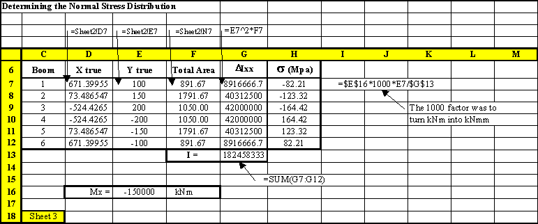
|
Figure 68: Excel sheet where the sectional properties and bending stresses of the idealised structure are calculated. |
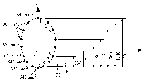
Mx = 100 kNm. If all direct stresses are carried by the booms, determine the
average direct stress in each boom.
|
Figure 69: Idealised fuselage cross section. |
moment equations reduces to:
![]()
![]()
![]()
Now that we have the position of the neutral axis, the best way to determine the stresses in each boom is by using a table
| Boom | y (mm) | B (mm2) | DIxx = By2 (mm4) | sz (MPa) |
|---|---|---|---|---|
| 1 | 661.5 | 640 | 2.8005e+08 | 35.67 |
| 2 | 601.5 | 600 | 2.1708e+08 | 32.43 |
| 3 | 421.5 | 600 | 1.0660e+08 | 22.73 |
| 4 | 229.5 | 600 | 3.1602e+07 | 12.37 |
| 5 | 26.5 | 620 | 4.3540e+05 | 1.43 |
| 6 | -202.5 | 640 | 2.6244e+07 | -10.92 |
| 7 | -394.5 | 640 | 9.9603e+07 | -21.27 |
| 8 | -500.5 | 850 | 2.1293e+08 | -26.99 |
| 9 | -538.5 | 640 | 1.8559e+08 | -29.04 |
| Ixx = | 1.8546e+09 |
Note: Because of symmetry, this table doesn't contain values for the booms on the left hand
side of the y-axis. However when calculating the second moment of area Ixx, the values
of DIxx for booms 2 - 8 were multiplied by 2 when doing the summation.
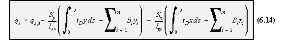
SHEAR OF OPEN SECTION BEAMS
The equation for shear flow for an open beam section was found to be equation 4.12:
that it could either be equal to : tD = t, if the skin was fully effective in carrying direct stress, or
tD = 0, if skin was assumed to carry only shear stresses. So:

value of 'tD' may or may not be equal to zero. This equation, however does not consider the effect of the idealised booms to the overall shear
flow. To account for this, we need to consider the equilibrium of one such boom.
|
Figure 70: Shear loaded open beam with booms, and equilibrium of ith boom. |
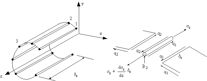
![]()
![]()

were present, their presence becomes an additive one, such that for a beam with 'n' booms,
equation (6.8) becomes:
can be simplified to have only the summation terms. To give:

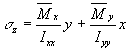
i due to the shear flow in skin segment i-1 and the change of shear flow due to the boom k
separating these two skin segments, Figure 71.
|
Figure 71: Sketch of skin segments i and i-1 and boom k to show how the shear flow is determined. |
area of boom k of coordinates xk and yk about the structures' centroid is:

segment (i - 1) and the change in shear flow due to boom k ( Dqk), equation (6.13).

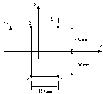
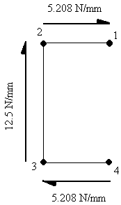
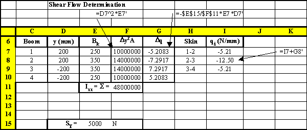
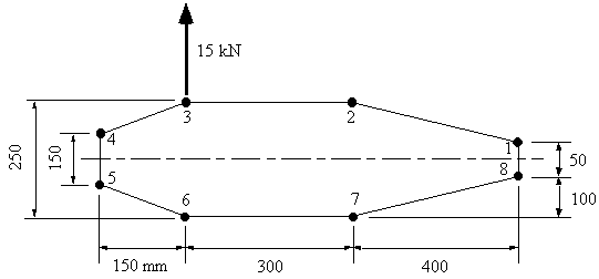
booms always has a constant value. Example 9: Calculate the shear flow in the following channel section. The skin is only
effective in shear (tD=0), area of all booms 1 & 4 = 250 mm2 , areas of booms 2
& 3 = 350 mm2.
|
Figure 72: Open channel with 5 kN force applied through shear centre. |
6.11 becomes:
![]()
| 1) |  |
| 2) |  |
| 3) |  |
| 1) | 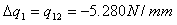 |
| 2) | 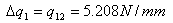 |
| 3) | 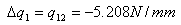 |
| 4) | 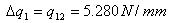 |
| 1) | 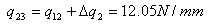 |
| 2) | 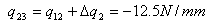 |
| 3) | 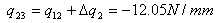 |
| 4) | 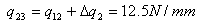 |
| 1) | 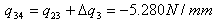 |
| 2) |  |
| 3) | 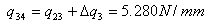 |
| 4) |  |
|
Figure 73: Shear flow distribution around channel of example 7. |
|
Figure 74: Excel sheet indicating how this problem can be solved |
SHEAR OF CLOSED SECTION BEAMS
The derivation of the equation to determine this shear flow is identical as the analysis for openbeam sections, making equation (4.15) look like this:

using equation (6.11) or (6.13). qs,0 in the residual shear flow due to making the closed beam into an open beam
section. It can be calculated using equations (4.19, 4.26 or 4.27) depending if we
know the location of the applied load (4.19), or if we are trying to determine
the shear centre (4.26 or 4.27).
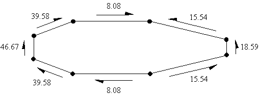
Example 10: Determine shear flow in the following wing structure with an applied vertical
load in the plane of booms 3 and 6. This structure has been idealised into direct
stress carrying booms and shear only stress skin (ie tD = 0). Boom areas are: B1
= B8 = 200 mm2, B2 = B7 = 300 mm2, B3 = B6 = 400 mm2, B4 = B5 = 150 mm2.
|
Figure 75: Closed wing section with applied shear force between booms 3 & 6 |
6.7. Only a vertical load is applied, Sx=0. Reducing equation 6.7 to:

Substituting this into the above equation gives:

doing the analysis in a counter clockwise sense we get:
![]()
![]()
![]()
![]()
![]()
![]()
![]()
![]()
the position of the applied force. Or we could take moments anywhere about the line of action
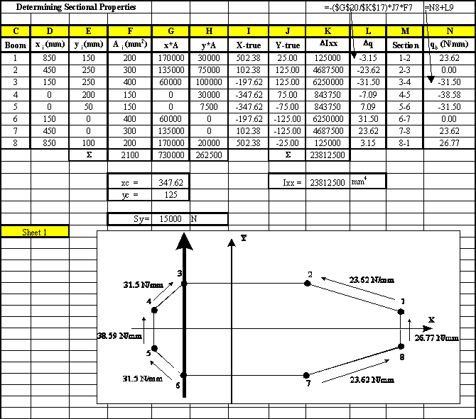
of the applied force, both these statements mean the same thing. Taking moments about point 3, gives: 0 = ( q4,5x150x150 + q5,6xx158.11x237.17 + q6,7x300x250 + q7,8x412.31x315.3 + q8,1x50x700
+ q1,2x412.31x72.76) + 2x165,000qs,0 giving that qs,0 = -8.08 N/mm From equation (ii) above we have that qs = qb + qs,0 , so:
qs12 = 23.62 - 8.08 = 15.54 N/mm
qs23 = 0 - 8.08 = -8.08 N/mm
qs34 = -31.5 - 8.08 = - 39.58 N/mm
qs45 = -38.59 - 8.08 = - 46.67 N/mm
qs56 = -31.5 - 8.08 = - 39.58 N/mm
qs67 = 0 - 8.08 = - 8.08 N/mm
qs78 = 23.62 - 8.08 = 15.54 N/mm
qs81 = 26.67 - 8.08 = 18.59 N/mm
|
Figure 76: Shear flow distribution of loaded closed wing section |
|
Figure 77: Spread sheet where the open beam shear flows are calculated |
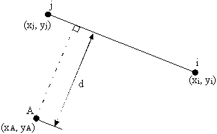
sheet example. However, in order for the spread sheet to calculate the perpendicular distance between a point
in space and a segment of skin equation (6.16) was used, with reference to Figure 78.
|
Figure 78: Perpendicular distance d between a point A and skin segment i-j |


|
Figure 79: Excel sheet showing the calculation of qs0 and the final shear flow distribution |
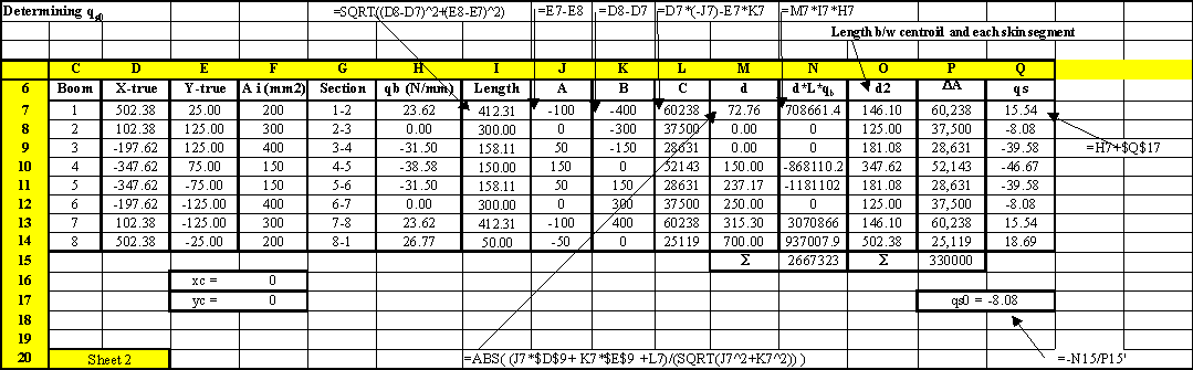
value of cell P15 is equal to 2A, twice the enclosed area of the wing section