All aircraft structures, particularly wings and fuselages, as well as supporting direct shear loads
must support an applied torque. In a fuselage, a torque can be generated by the loads applied
to the vertical fin. In a wing a torque can be generated by the resultant pressure distribution
acting a distance away from the cross section's shear centre. This chapter deals with determining
the shear flow distribution due to an applied torque.
TORSION OF CLOSED BEAM SECTIONS
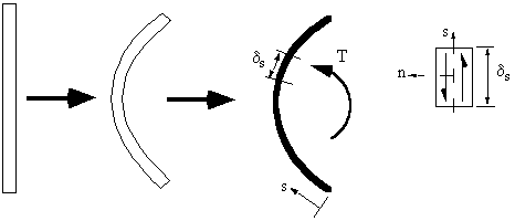
A beam with a closed section experiencing only a pure torque T and without any axial
constraints, does not develop direct stresses, ie s z = 0.
So equations (4.2) and (4.3) become:
![]()
The only way to satisfy these equations would be if the shear flow 'q' was constant.
varied with 's'.
|
|
|
Figure 45: Closed beam with applied torque. |
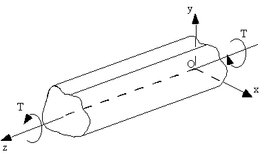
To determine the relationship between applied torque and shear flow, apply equilibrium to
the end of the beam. In essence the applied Torque T must equal to the torque generated by
the shear flow.
|
Figure 46: Equating applied torque with moment generated by shear flow. |
section gives:
![]()
![]()

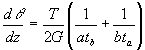
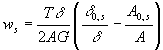
rate of twist due to the Torque 'T':

becomes:


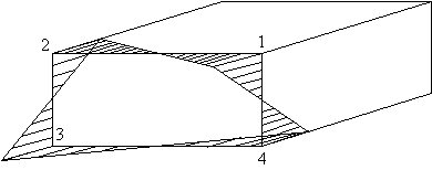
symmetrical, rectangular section when subjected by counterclockwise torque T.
Assume G is constant.
|
Figure 47: Torsion of rectangular beam section. |
![]()
![]()
where:
![]()


that we need only look at the corners because here the warping is the greatest. At 1:
|
Figure 48: Warping distribution of closed beam with applied torque. |
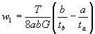
b) if b/tb = a/ta the section has ZERO warping
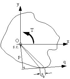
TORSION OF OPEN BEAM SECTIONS
To do this analysis we need to consider torsion of a thin rectangular strip, which is bent to formthe open section.
|
Figure 49: Open beam section subject to torque. |
The equation for rate of twist is:


thickness of the section and is given by:


thickness. This is much less than the warping of the centre line of the section and is
ignored in aircraft structural analysis.
The shear strain is given by equation (4.5):
![]()
Shifting the axis of the beam to coincide with the shear centre, makes equation (4.9) become:
![]()
Shear stress is given by:
![]()
Combining these 3 equations give:
![]()
![]()

where:

and
AR is the area swept out by a generator, about the shear centre, from the point of zero warping.
Note : AR is positive if movement of PR along the tangent to the surface in the direction
of 's' leads to a counterclockwise rotation of PR about the shear centre.
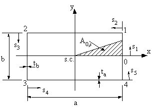
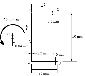
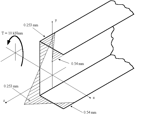
Example 6: Determine the maximum shear stress t max, the rate of twist and the warping for
the open beam channel section of Figure 50 when a torque of magnitude T = 10 Nm
is applied at the shear centre. Assume the material shear modulus to be and G = 25 GPa.
|
|
|
Figure 50: Open beam with applied torque of 10 kNmm. |
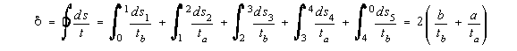
a) Determining sectional property
![]()
b) Determining maximum shear stress
![]()
c) Determining rate of twist
![]()
d) Determining the sections warping
![]()
where:

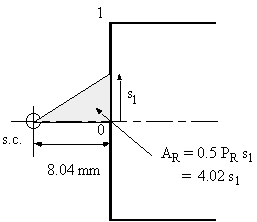
Because the section is symmetrical, at 0, s1 = 0, w = 0. Therefore, between 0 and 1:
|
|
|
Figure 51: Diagram showing the derivation of AR |
![]()
|
Figure 52: Diagram indicating the construction of AR02. |
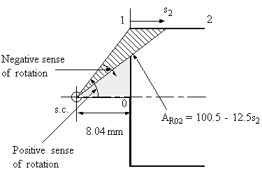
![]()
As the section is symmetrical, warping on the lower section will be the reverse of this. The warping distribution looks like this:
|
|
|
Figure 53: Warping distribution for channel section with 10 kNmm torque. |
Note : If the section is unsymmetrical and you don't know where ws = 0, use the following
equation.

A R,0 = Swept area by generator rotating about the shear centre from some convenient origin
and
where :
![]() section = Integral over the entire perimeter of the section
section = Integral over the entire perimeter of the section