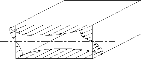
STRESS, STRAIN AND DISPLACEMENT RELATIONSHIPS FOR OPEN AND CLOSED SINGLE CELL THIN WALLED BEAMS
Assumptions:
1) Axial constraint effects are negligible
2) Shear stresses normal to surface can be neglected
3) Direct and shear stresses on planes normal to surface are constant across thickness
4) Beams have uniform section, with skin thickness varying around the section but constant
along length of the beam
tube/beam from some convenient origin. For a loaded beam, look at an element of size ds x dz x t of its wall showing all shear and direct
stresses necessary to keep it in equilibrium.
|
|
Figure 23: Loaded beam structure. |
Figure 24: General stress system on element of closed or open beam section. |
pressures. Although 't' can vary with 's' for each element of length ds, we can assume that
this length is small enough to make 't' constant over this length.
From Elasticity we have that:
![]()
Instead of using shear stress, the analysis will become easier if we introduce the term Shear
Flow q , which is the shear force per unit length rather than shear stress. It is represented by:
![]() (4.1)
(4.1)
What we are attempting to determine in this analysis are two things, firstly a relationship
between the shear and direct stresses, and secondly a relationship between shear strain and
the deformation of this element. So we may then use these relationships to determine a
shear flow equation and an angle of twist equation.
|
|
|
Figure 25: Element showing the direct stresses and shear flow. |

![]() (4.2)
(4.2)
![]() (4.3)
(4.3)
displacement at a point on the tube wall.
|
Figure 26: Axial, tangential and normal components of displacement of a point in beam wall. |
w = displacement in the z axis
vt = tangential displacement, positive with increasing 's'
vn = normal displacement, positive outwards
From Elasticity :![]() (4.4)
(4.4)
|
Figure 27: Element distorted due to shear. |
![]()
![]() (4.5)
(4.5)
able to hold the cross section rigidly enough so that when it twists it holds its cross sectional
shape. However the ribs have no strength in a plane normal to them, allowing the section to
warp or deform in the z axis.
Define
y = Angle between the tangent to the surface of the beam's cross section and the x-axis.
 |
| Figure 28: Beam cross section rotated by angle q, showing the rotation of the normal to surface. |

 |
| Figure 29: Rotation of beam section about centre of twist |

![]()

determine the second term of Equation (4.5) it is necessary to differentiate Equations (4.6)
and (4.7) with respect to z.
![]() (4.8)
(4.8)
![]() (4.9)
(4.9)

or closed tube, as well as the displacement, warping and angle of twist of the section due to
these shear loads. SHEAR FLOW IN BEAMS WITH OPEN SECTIONS
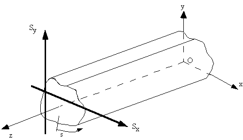
Look at a beam with an open section, with applied shear forces Sx and Sy about a point which
produces no twisting of the tube cross section (Shear Centre).
|
Figure 30: Open beam section loaded with two shear loads (Sy and Sx) |
![]()


by a single vertical force applied through the shear centre.
|
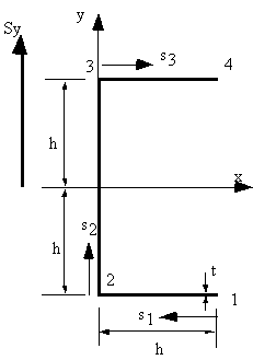
Figure 31: Channel section loaded vertically through shear centre. |
beam, so shear flow equation (4.13) applies. Since only Sy is applied, then:

![]() ,
, ![]() ,
, ![]()
Which gives that
![]() ,
, ![]()
So equation (4.13) becomes:

On the bottom flange 12, at s1 = 0, y = -h and at s1 = h, y = -h which by using the equation of a
line y = ms1 + b gives that: y = -h, where 0 < s1 < h so the shear flow between points 1 and 2
is:


a linear increasing shear flow.
On the web 23, at s2 = 0 , y = -h and at s2 = 2h, y = h which by using the equation of a line y =
ms2 + b gives that y = - h + s2, where 0 < s2 < 2h , but at point 2 the shear flow is not 0
so:


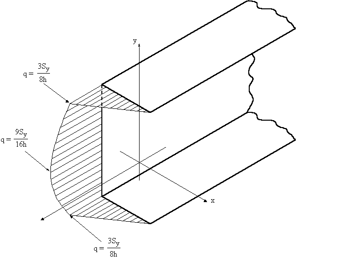
shear flow at s2 = h, of q23 = 9Sy / 16h, and at s2 = 2h, q3 = 3Sy / 8h. On the top flange 34, at s3 = 0, y = h and at s3 = h, y = h which by using the equation of a line
y = ms3 + b gives that y = h, where 0 < s3 < h so the shear flow between points 3 and 4 is:


|
Figure 32: Shear flow distribution on channel section |
SHEAR CENTRE OF OPEN BEAM SECTION
The shear centre is that point in the cross section through which the shear loads produce no
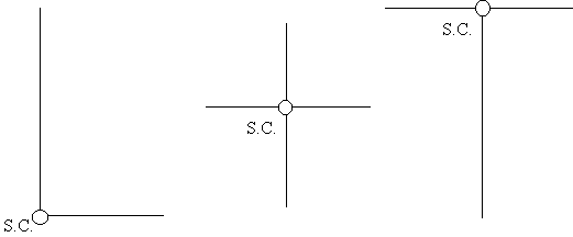
twisting. It is also the centre of twist when torsional loads are applied. As a rule, if a cross-
section has an axis of symmetry, then the shear centre must lie on that axis and in cruciform
or angle sections, the shear centre is located at the intersections. It is important to define the
position of the shear centre because although most wings are not loaded at this point, if we
know its location, we can represent the shear loads applied as combinations of shear loads
through the shear centre and a torque.
|
Figure 33: Shear centre locations for some typical open beam sections. |
appropriate point in the cross section. This moment is equal to the moment generated by the
applied shear force about this same point.

|
Figure 34: Channel section with load through shear centre. |
web. The steps in determining the shear centre are as follows:
1) Determine the equations which describe the shear flow in the cross section, (done).
These were found to be:![]()

![]()
point 3. This eliminates the moments caused by the shear flow in the web 23 and flange 34. The moment equation is:


![]()
to be found. This is best achieved by first applying a vertical shear force Sy,
determining scx, then applying a horizontal force Sx determining scy.
SHEAR FLOW OF CLOSED TUBES
This solution is similar to that for an open beam section but with 2 differences:1) Shear loads may be applied through any point in cross section;
2) At origin of 's', the value of shear flow qs,0 is unknown
Look at arbitrary closed beam, with applied shear forces Sx and Sy
|
|
|
Figure 35: Closed beam section with two shear loads (Sy and Sx) |
If hoop stresses and body forces are absent, it is necessary to use equation 4.2:
![]()
and as for the analysis of open beam sections, when substituting for sz, we obtained:

However unlike for open beams, at s = 0, qs0![]() 0, so when integrating we get:
0, so when integrating we get:

The first two terms are identical to the equation of shear flow of open tube loaded through shear
centre. If we let this terms be ‘qb’ then:

shear flow distribution is then given by the following equation, which is equation (4.13).

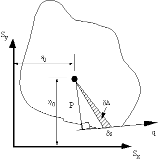
the beam was cut. To do this, look at beam cross section loaded at some point:
|
Figure 36: Resolving moments due to applied loads and shear flow about a point. |


are taken, then:
![]()
![]()

A = Area enclosed by the mid-line of the beam section wall

becomes:

TWIST AND WARPING OF SHEAR LOADED CLOSED SECTIONS
If a shear load is not applied at the shear centre, the closed beam section will both twist and havean out of plane axial displacement (warp). From equation (4.1) shear flow is defined as:
![]()
![]()
![]()
![]()


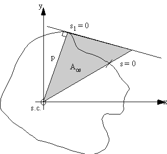
If however, equation (4.20) was integrated wrt 's' from some origin point on the surface of the
beam to any other point in the cross section, with the axis origin at the shear centre, it gives:


|
Figure 37: Beam section showing area swept by generator. |
singly or doubly symmetrical, at the axis of symmetry the warping would be zero. If the origin
of 's' was taken at any of these points then at s = 0, w0 = 0 and the rest of the warping would be
easily found. For unsymmetrical sections, the unknown warping displacement at s = 0 is given by:

SHEAR CENTRE OF CLOSED BEAM SECTIONS
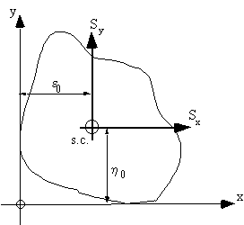
The position of the shear centre for a beam loaded as shown in Figure 38, can be found by usingequation (4.17).
![]()
ho = vertical distance from x-axis to shear centre from reference axis
eo = horizontal distance from y-axis to shear centre from reference axis
|
Figure 38: Determining location of the shear centre for closed beam section. |
centre, if a shear load is applied here, it produces no twist, so by using equation (4.21) :
![]()
![]()


beam section can now be determined.
Example 4:
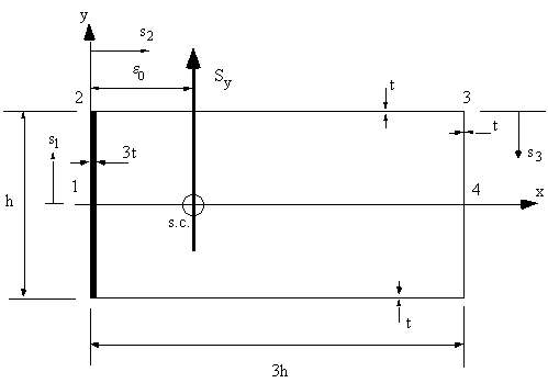
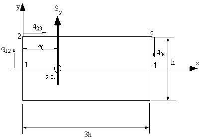
Determine shear flow, shear centre and warping in the following closed beamsection loaded with a shear force Sy at the s.c.. G is constant .
|
Figure 39: Closed section of question 5. |
1) Determine sectional properties
Since section symmetrical Ixy = 0, and since only loaded vertically , only need Ixx, which is:
![]()
![]()
2) Determine Shear Flows
Between 1 and 2, y = s1 and at s1 = 0 , q1 = q0![]()
![]()


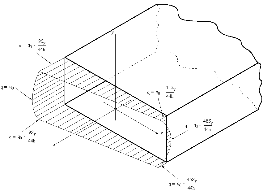
The shear flow distribution will look like this:
|
Figure 40: Shear flow distribution with constant q0 |
3) Determine q0
Because 't' is not constant, equation (4.26) becomes:


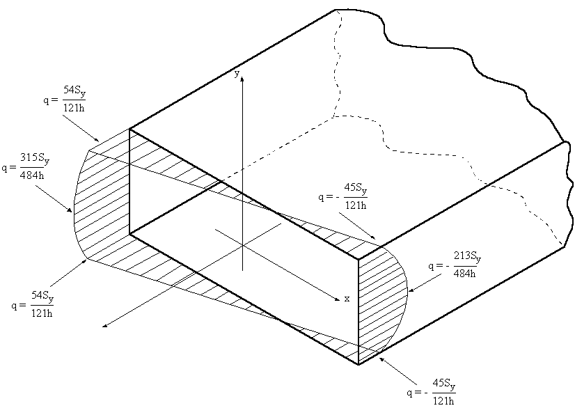
|
Figure 41: Shear flow distribution of closed beam. |
4) Determine Shear Centre
To determine the shear centre you can use equation (4.18 mod.) or since qs,0 was found, useequilibrium. If you use the latter it a lot easier.
|
Figure 42: Closed beam indicating applied shear force and the direction of the shear flow. |


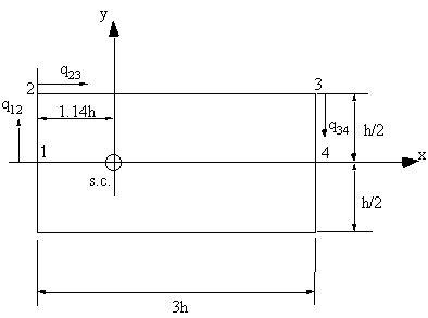
This is done using equation (4.22) but first the axis must be moved to the shear centre:
|
Figure 43: Closed beam with axis shifted to shear centre. |

that


magnitude but opposite in direction. If this is plotted, it looks like this:
|
Figure 44: Diagram showing the warping distribution on the closed beam. |


