Test 1
Try to solve the problems first and see if the answer you have chosen is correct. For detailed explanation click on Explain button.
1. In the structure shown below members ABC and BDE are assumed to be solid rigid members. Member BDE is supported by a roller at point E, and is pinned to member ABC at point B. Member ABC is pinned to the wall at point A. Member ABC is a aluminum rod with a diameter of 1 inch. For this structure: How many reaction forces are in joints A and E
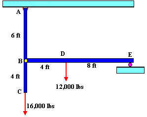
For A two reaction forces and for E one
Two reaction forces for each one
Draw a Free Body Diagram showing all support forces and loads.
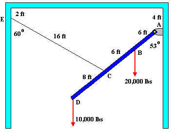
2. In the structure shown below member ABCD a solid rigid member pinned to the wall at A, and supported by steel cable CE. Cable CE is pinned to the wall at E and has a diameter of 1 inch. For this structure:
Draw a Free Body Diagram showing all support forces and loads.